INDEX
Energy meter
System can have multiple types of an energy meters.
- Main energy meters - located at the break-up point, right after the distribution energy meters. These meters are used to control the power plant from distribution network point of view.
- PV energy meters - used to measure total amount of electricity produced by PV plant reduced by power losses (not necessary for system to operate).
- Auxiliary energy meters - used to measure energy at user defined places (not necessary for system to operate).
Main energy meter
Located at "Electricity\Energocenter\"
PV energy meter and auxiliary meters
Located at "Electricity\"
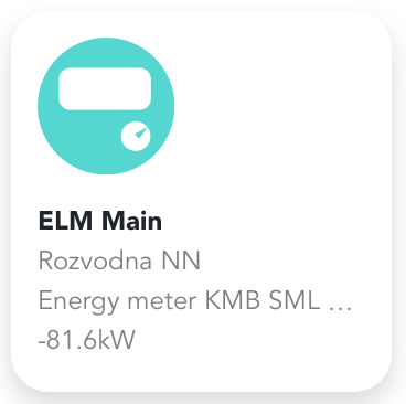
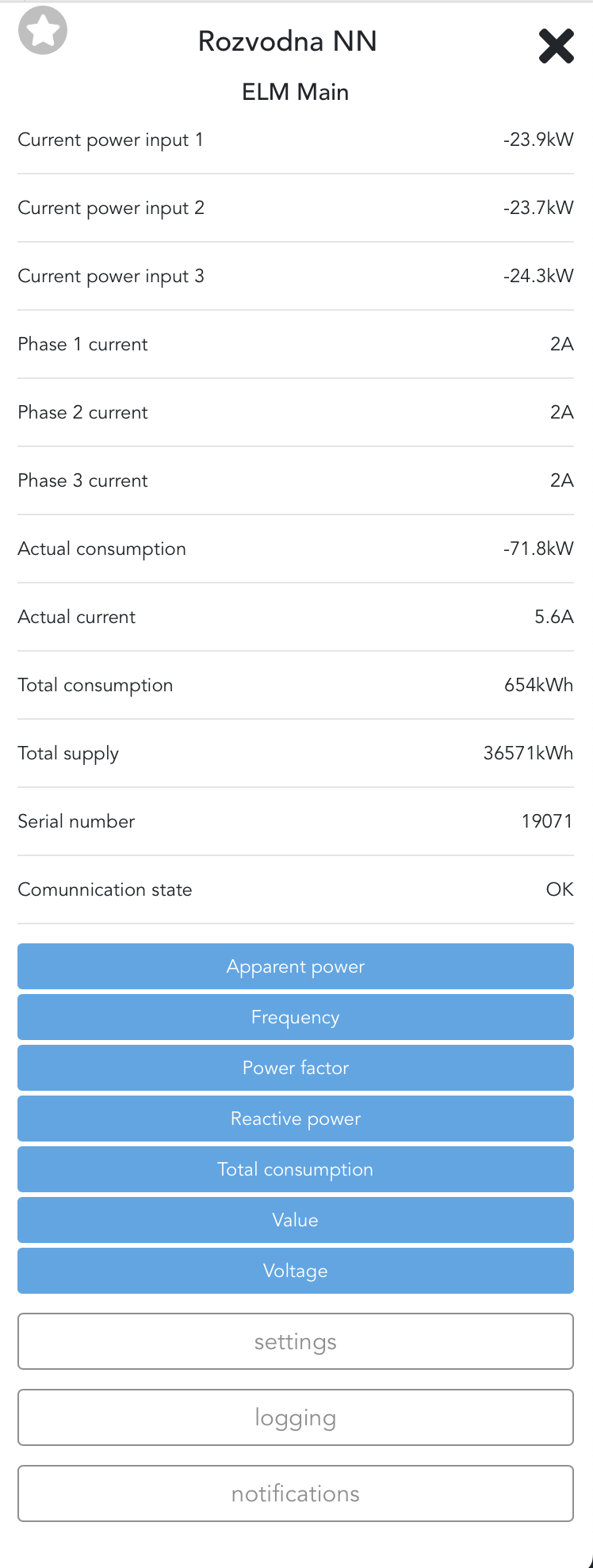
Device is showing at the bottom actual consumption value. More information can be found after clicking on the device. Besides information about phase power, current, frequency or for example power factor, it is also possible to turn on logging of values measured by energy meter. These values can be used again in dashboards or for troubleshooting.
Basic user permissions does not allow to change settings. With higher permissions it is possible to set the energy meter address (either IP address, or Modbus ID).
Side-menu
Advanced view of energy values is available in side-menu.
Settings
[High privileges required]
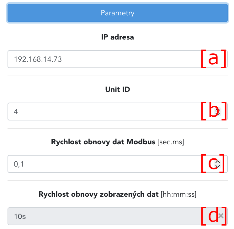
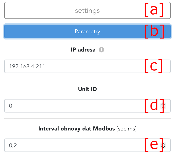
Following values can be edited for energy meter connected with Modbus TCP.
[a] - IP address of energy meter
[b] - Modbus ID of device
[c] - Data refresh time via Modbus
[d] - Refresh time of shown data
Following values can be edited for energy meter connected directly via Modbus RTU.
[a] - Modbus ID of device
[b] - Speed of modbus link
[c] - Parity of transmission
[d] - Data refresh time via Modbus
[e] - Refresh time of shown data

Inverters and loggers
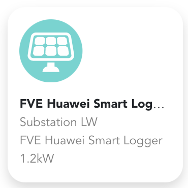
PV inverters can by connected directly via Modbus, or through Loggers (like Smart Logger). In first case, all controlled inverters will be listed under Energocenter. In second case, only logger will appear and all communication goes only to logger.
In both cases devices have to be properly configured. Loggers often need to enable "remote control" via their web interface, to listen to commands send from Energocenter.
Devices displays at the bottom actual power production. More information can be shown after clicking on device. Based on user permissions different settings are available. Simple user cannot change settings, with higher permissions it is possible to change address, maximal power, dispatch control, manual control and others.

Side-menu
[a] - PV power plant power
[b] - Maximum power in percentage, that each inverter can produce
[c] - Reactive power of PV power plant
[d] - Sum of energy created
[e] - Required power of PV power plant
[f] - Power control mode
[g] - Inverter mode
[h] - Communication status

Settings
[High privileges required]
Under settings [a], it is possible to configure connection settings [b].
[c] - IP address of inverter or logger
[d] - Modbus ID of device
[e] - Modbus data refresh
Under settings [a], it is possible to block communication [b].
[c] - Stops data loading over Modbus
[d] - Energy storage will not be controlled by Energocenter

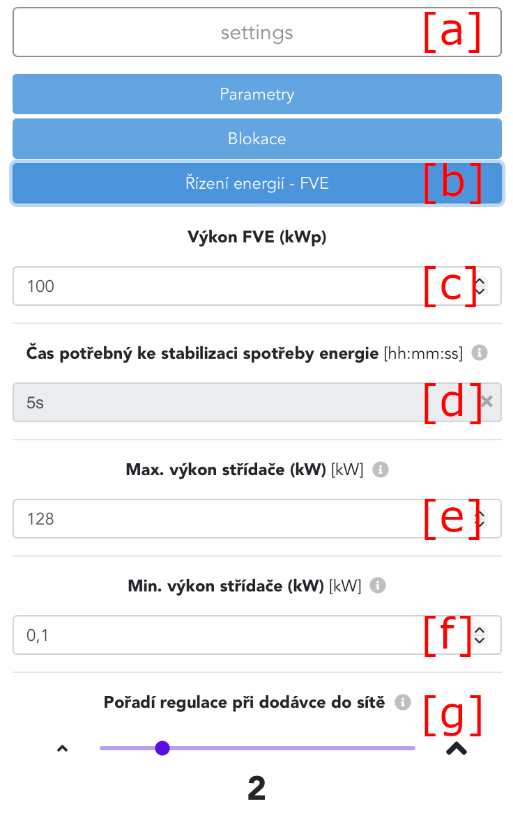
Under settings [a], it is possible to configure energy management of power plant [b].
[c] - Power of PV panels installed
[d] - Time required for change to appear on energy meter, after turning on/off the charging. During this period, no other device will be turned on
[e] - Maximum total power of inverters
[f] - Minimal power of inverters (we do no recommend to set 0kW, since it often causes that inverters are switched to sleep mode and then after changing to non zero values, the waiting period is started before start - usually around 300s)
[g] - Order in which device is turned off, to prevent overloading of main circuit breaker. Usually 1 is for batteries, 2 for PV inverters.
Under settings [a], it is possible to configure dispatch control [b].
To enable dispatch control of power plant, enable option [c].

Battery storage and DC inverters
Battery storage as a component, or inverters and batteries as devices, can be connected via Modbus, or through Loggers (like Smart Logger).
In case of direct connection, multiple devices are created. Battery inverter (in this case Pramac) is the main component. Batteries connected to this inverter are accessible after clicking on the icon in right top corner.

List of batteries connected to inverter displayed after clicking on the icon.

When connected via Logger, icon of a BESS appears only as one device (for example "ESS Luna").
Side-menu
[a] - energy consumption from distribution network, negative values represents export of energy
[b] - maximal inverter power (actual inverter power)
[c] - required inverter power (value requested from energocenter)
[d] - required inverter reactive power
[e] - inverter status
[f] - communication status
[g] - current turn on order
[h] - 1/4 hour control status
[i] - additional information about energy
[j] - additional values about battery inverter
[k] - allowed settings
[l] - logging of possible values from component
[m] - possible error notifications of component

Settings
[High privileges required]
Under settings [a], it is possible to configure Parameters [b].
[c] - IP address of BMS of battery inverter.
[d] - Modbus data refresh interval.
[e] - Whether set minimum and maximum battery voltage manually or automatically from batteries itself.
[f] - Used when [e] is disabled. Specify the maximum battery voltage.
[g] - Used when [e] is disabled. Specify the minimum battery voltage.
[h] - Enables the EMS management of battery.

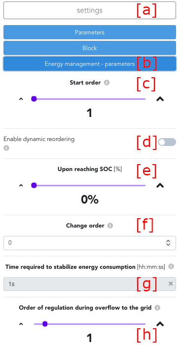
Under settings [a], it is possible to configure Energy management parameters [b].
[c] - Order of storage charging from PV. Value must be non zero.
[d] - Dynamic reordering means, that battery will change order when configured SOC is reached.
[e] - Used when [d] is enabled. Specify the SoC value for order change.
[f] - Used when [d] is enabled. Specify the new battery order after SoC has been reached.
[g] - How long it takes for energy meter to see that charging started/stopped. During this time next device in sequence will wait.
[h] - Order in which will device be controlled in order to prevent circuit breaker overload or exceeding power distribution limits. Order 1 is limited first. Usually 1=batteries and 2=PV.
Errors
In case, component is in error, error icon will appear in top left corner.

In such case, more information about error can be found after clicking on a component. As seen below, state is now "EMS control disabled" as a reaction to this error, and error indicator is now green.
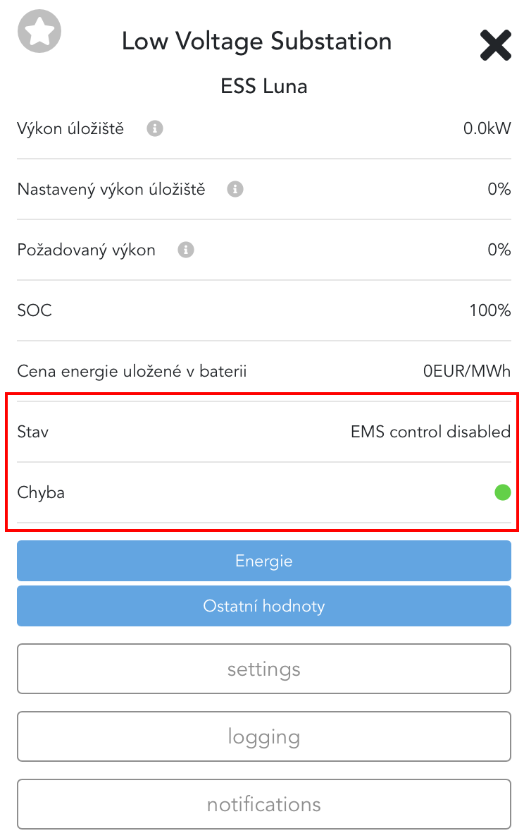
After problem is solved, it is sometimes required to turn on EMS control manually (in case automatic recovery from error is turned off).
Was this article helpful?
That’s Great!
Thank you for your feedback
Sorry! We couldn't be helpful
Thank you for your feedback
Feedback sent
We appreciate your effort and will try to fix the article